How to build a simple blinking led circuit with a capacitor, transistor and two resistors
Here’s how you blink an led with just an led, capacitor, transistor and two resistors. This post is a complement to Dick Cappel’s “Simplest LED Flasher Circuit” post. I’ve added a Fritzing diagram and some high-res photos and video so that you can quickly build the circuit. Most of the other videos online are from a very long time ago and are mostly out of focus. You’ll see a bunch of people asking for an in-focus video in the comments of this video. I’m hoping this detailed post helps.
Here’s what you’ll need:
- Breadboard
- 1 x Led
- 1 x Transistor PN2222 – I used an NPN resistor, but you could use an PNP you just need to turn it around and use ground instead of power to source it. Here’s a good video that describes the difference between NPN and PNP.
- 1 x Capacitor – The capacitor size determines the speed of the blink. I experimented with 100uf/6.3v and 1000uf/10v and both worked.
- 1 x 1k ohm resistor
- 1 x 100 ohm resistor
- 12v Power Supply – I used 8 x AA batteries connected in series. I also tried with 6 and 9v supplies, but only got it working with 12v.
Breadboard setup
[
-
Connect your batteries in series (negative connected to positive)
-
Connect 1k ohm resistor from positive to a row in the middle of the board.>

-
Connect capacitor positive lead to 1k ohm resistor and negative lead back to ground>
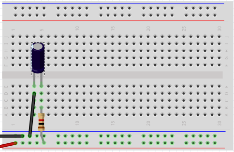
-
Connect transistor’s emitter in between the 1k resistor and the capacitor’s positive lead. Connect the collector a couple of holes over. Don’t connect the base. Hold the transistor with the flat side facing you. The pin on the left is the emitter, the pin on the right is the collector, the pin in the middle is the base. Good diagram here explaining that.>

-
Connect led’s positive lead (the long one) to the transistor’s collector and connect the negative lead to the 100 ohm resistor and connect that to ground.>
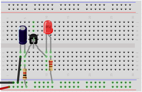


That’s it. It should start blinking.
Here’s a video of it working.
And here’s an up close photo of the circuit.

Jon
Share on LinkedIn
Quick Share: Your custom post text has been copied to your clipboard! Click the button below to open LinkedIn's share dialog, then paste it.
💡 Tip: LinkedIn will open in a new tab. Use Ctrl+V (or Cmd+V on Mac) to paste your text.
Note: LinkedIn will show the article preview. You can add your custom text above it.